
TM 5-3825-213-35
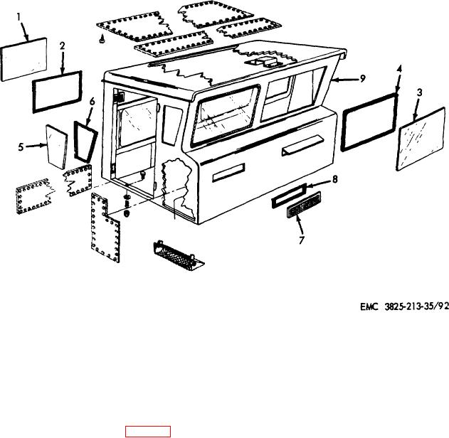
1
Rear window (2 rqr)
6
Weatherstrip (2 rqr)
2
Weatherstrip (2 rqr)
7
Vent screen (2 rqr)
3
Windshield (2 rqr)
8
Weatherstrip (2 rqr)
4
Weatherstrip (2 rqr)
9
Cab assembly
5
Side window (2 rqr)
Figure 92. Windshield, side and rear windows, removal and instruction.
(9) Install the plow hydraulic manifold (TM 5-
(5) Install the steering wheel (par. 281).
3825-213-20).
(6) Connect the primer lines (TM 5 3825-213-
(10) Install defroster manifold and tubes (TM 5-
20).
3825-213-20).
(7) Connect all air and hydraulic lines (TM 5-
(11) Install the lights and horn assemblies (TM 6
3825-213-20).
3825-213-20).
(8) Connect instrument panel wiring (TM 5-
3825-213-20).
Section XII. CARRIER FRONT FENDERS, FLOORBOARD, AND FLOORMAT
the right and left side operator's cab platform. The
306. General
floorboard is mounted on the carrier frame between the
The front fenders are constructed of welded steel plates
two
and braced with channel iron. The front fenders serve as
218