
TM 5-3825-213-35
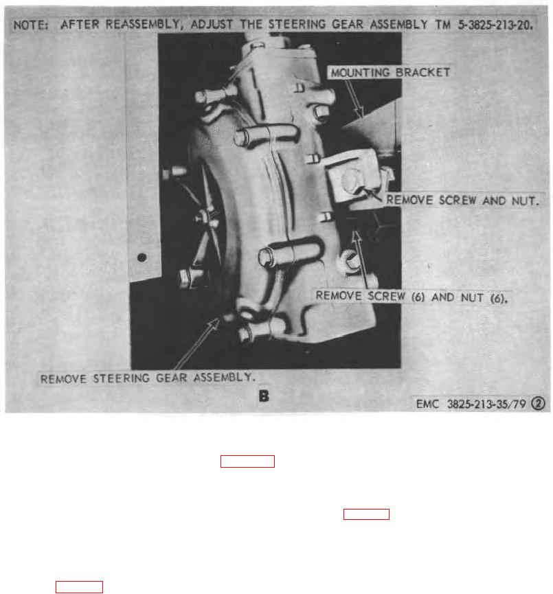
B. Gearbox removal points.
Figure 79-Continued.
b. Inspection and Repair. Inspect all parts for
b. Installation.
defective condition. Replace or repair worn, damaged,
(1) Install the steering gear assembly is instructed
or defective parts.
on figure 79.
(2) Install the horn button assembly (TM 5-3825-
281.
Steering Gear Assembly Reassembly and
213-20).
Installation
(3) Install the turn signal assembly (TM5-3825-218-
a. Reassembly. Reassemble the steering gear
20).
assembly in the reverse of numerical sequence
(4) Install the control valve (TM 5-3825-213-20).
illustrated on figure 80.
(5) Install the steering sector gearbox shield (TM 5-
Note.
3825-213-20).
Shaft bushing should be reamed to
0.0005 inch clearance. The maximum
allowable clearance is 0.0025 inch.
200