• Home
  • Download PDF
  • Order CD-ROM
  • Order in Print
Figure 82. Ball joint assembly, removal and installation.
Figure 83. Front and rear ball joint and axle shaft assembly, disassembly and reassembly, exploded view - Continued

Field Maintenance Manual Snow Removal Unit, Self-Propelled: Gasoline Driven; Rotary; Wheel Mtd; Winterized Page Navigation
  194    195    196    197    198  199  200    201    202    203    204  
img
TM 5-3825-213-35
1
Screw-, cage ring, special
6
Pin, trunnion bushing (2 rqr)
2
Cage ring
7
Trunnion bushing (2 rqr)
3
Cage ring
8
Pin, trunnion bushing (2 rqr)
4
Inner axle shaft
9
Turnnion bushing (2 rqr)
5
Outer axle shaft
10
Thrust washer
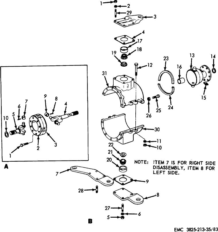
A. Front and rear axle shaft, exploded view.
Figure 83. Front and rear ball joint and axle shaft assembly, disassembly and reassembly, exploded view.
205


Privacy Statement
Press Release
Contact

© Copyright Integrated Publishing, Inc.. All Rights Reserved.