
TM 5-3825-213-35
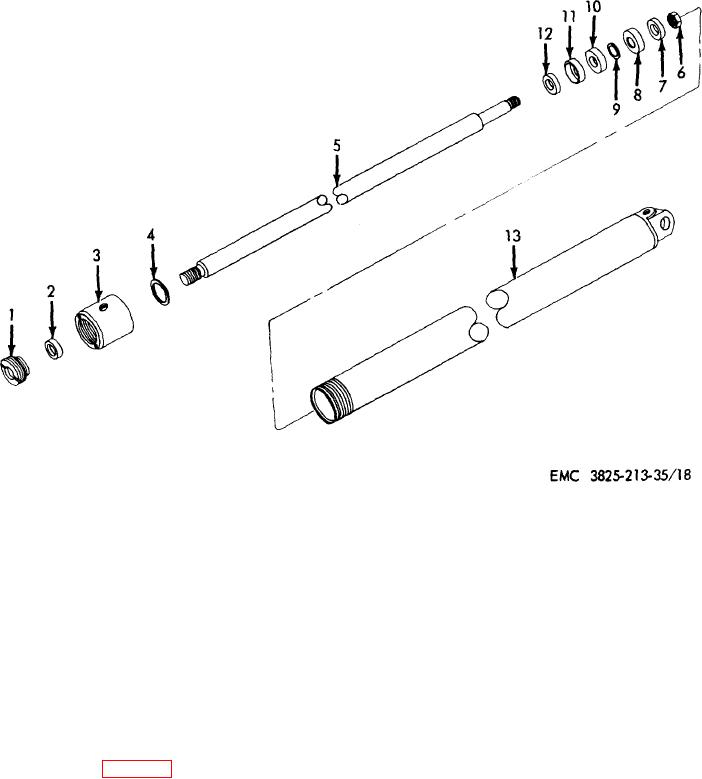
1
Nut, special
8
Cup
2
Packing
9
Preformed packing
3
Cap
10
Piston
4
Washer, special
11
Cup
5
Rod
12
Spacer
6
Nut, self-locking, 5/8-18
13
Body
7
Spacer
Figure 18. Snowplow fast housing rotating cylinder assembly, disassembly and reassembly, exploded view.
89.
Snowplow Fan Housing Rotating Cylinder
Note
Assembly Reassembly and Installation
Immerse cylinder parts in clean
hydraulic fluid to facilitate assembly.
a. Reassembly.
Reassemble the fan housing
rotating cylinder assembly in reverse of numerical
b. Installation. Install the fan housing
rotating
sequence illustrated on figure 18.
cylinder assembly (TM 5-825213-20).
Section III. SNOW CHUTE HYDRAULIC LIFT CYLINDER ASSEMBLY
controlled by the operator extends or retracts the snow
90. General
chute for the required distance for blowing the snow
during removal operation. It is a double-acting cylinder.
The snow chute hydraulic lift cylinder assembly
65