
TM 5-3825-213-35
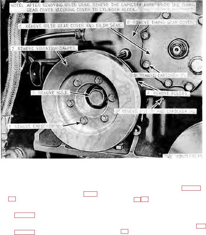
Figure 69. Plow and carrier engine vibration damper, idler gear, and timing gear cover, removal and installation.
245. Plow and Carrier Engine Timing Gear Cover and
(2) Install the tachometer drive and oil cooler
lines (TM 5-3825-213-20).
Idler Gear Reassembly and Installation
a. Reassembly.
(3) Install the water pumps (par. 216).
(1) Install the idler gear as illustrated on figure
(4) Install the plow and carrier engine (pars.
(2) Reassemble the timing gear cover in the
reverse of numerical sequence illustrated
Note.
on figure 70.
On the carrier engine also install the
generator plow hydraulic pump (TM 5-
b. Installation.
3825-9213-20), and compressor (fig.
(1) Install the timing gear cover as instructed
on figure 69.
167