
TM 5-3825-213-35
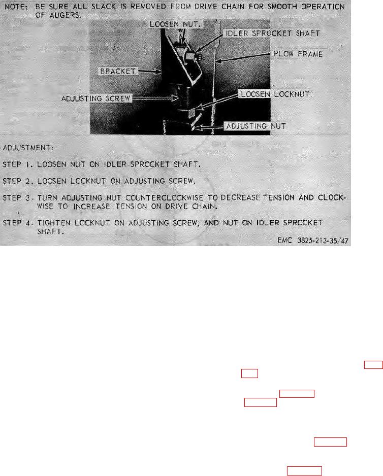
Figure 47. Drive chain adjustment.
Section IX. SNOWPLOW FRAME ASSEMBLY
(2) Remove the fan housing rotating
176.
General
cylinder (TM 5-3825-213-20).
The snowplow frame assembly houses all moving
(3) Remove the cutting edge and side
parts of the rotary. It is rigidly constructed to withstand
cutters (TM 5-3825-213-20).
the pushing of a large four wheel drive truck. The
(4) Remove the shoes and skates (TM 5-
scraper blade is the curved section directly back of the
3825-213-20).
lower auger. Trunnion bearings support the augers in
(5) Remove the auger drive shaft (par.
the frame assembly.
(6) Remove the fan and auger gearcase
177.
Snowplow Frame Assembly Removal and
assembly (par. 165), and fan housing
Disassembly
Removal.
Remove the snowplow frame
a.
(7) Remove the -augers (TM 5-3825-213-
assembly (TM 5-3825-213-10).
20).
b.
Disassembly.
(8) Remove the auger drive chain and
sprocket assemblies (par. 173).
(1) Remove the chute trough assembly (TM
5-3825-213-20).
(9) Disassemble the snowplow frame
assembly in numerical sequence as
illustrated on figure 48.
118