• Home
  • Download PDF
  • Order CD-ROM
  • Order in Print
Figure 44. Fan blower housing assembly, disassembly and reassembly, exploded view
Figure 45. Auger drive chain case cover, chain and sprocket assemblies, removal and installation - Continued

Field Maintenance Manual Snow Removal Unit, Self-Propelled: Gasoline Driven; Rotary; Wheel Mtd; Winterized Page Navigation
  105    106    107    108    109  110  111    112    113    114    115  
img
. . .
TM 5-3825-213-35
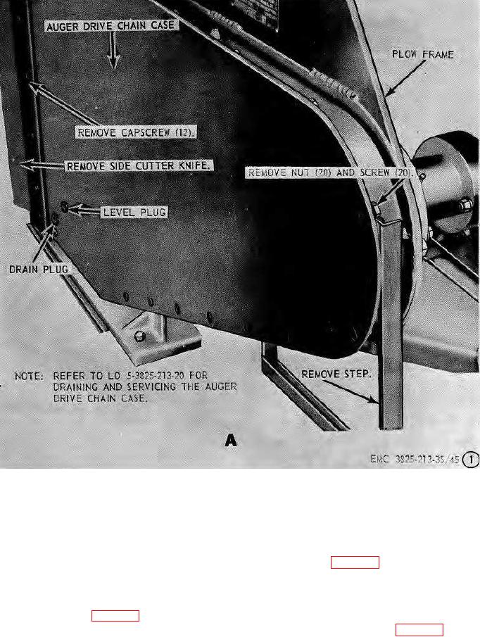
A. Case cover removal points.
Figure 45. Auger drive chain case cover, chain and sprocket assemblies, removal and installation.
(2) Install the drive chain as instructed on
175.
Auger Drive Chain and Sprocket Assemblies
figure 45.
Installation, Timing, and Adjustment
b.
Timing and Adjustment.
a.
Installation.
(1) Position the chain on the sprockets so
(1) Install  the  sprocket  assemblies
as
that each auger will set in proper
instructed on figure 45.
relation to the auger directly below it as
instructed on figure 46.
115


Privacy Statement
Press Release
Contact

© Copyright Integrated Publishing, Inc.. All Rights Reserved.