
TM 5-3825-213-35
NOTE
NOTE
It is sometimes necessary to move
Be sure all slack is removed from
the chain a tooth at a time until
drive chain for smooth operation of
proper setting is found.
augers.
(2) Adjust the drive chain as instructed on
(3) Install the case cover as instructed on
(4) Install snowplow on carrier (TM 5-3825-
213-10).
NOTE
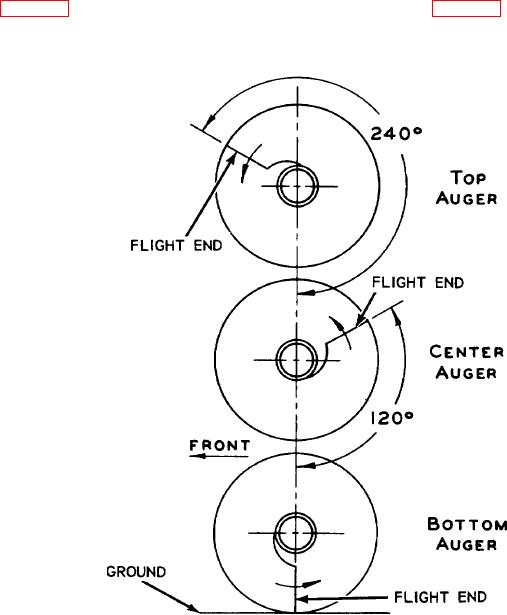
THE FLIGHT ENDS OF EACH AUGER FORMS A DIAGONAL LINE, ONE TO THE RIGHT AND ONE
TO THE LEFT.
TO TIME THE AUGERS, ALIGN THE BOTTOM AUGER FLIGHT ENDS
PERPENDICULAR TO GROUND. ALIGN THE CENTER AUGER 120 AHEAD OF THE BOTTOM
AUGER. ALINE THE TOP AUGER 120 AHEAD OF CENTER AUGER OR 240 AHEAD OF BOTTOM
AUGER.
EMC 3825-213-35/46
Figure 46. Auger settings for proper timing.
117