
TM 5-3825-213-35
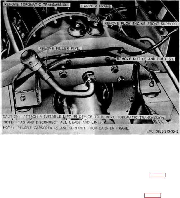
Figure 6. Torqmatic transmission assembly, removal and installation.
(6) Remove the plow drive shaft (TM 53825-
213-20).
(6) Install the front and rear drive shafts and
(7) Disconnect the shifter arm (TM 53825-
transmission to transfer case jack shaft
213-20).
(TM 5-3825-213-20).
(8) Remove the plow transmission assemble
53. Plow Transmission Assembly
as instructed on figure 4.
a. Removal.
b. Installation.
(1) Drain plow engine coolant system (TM 5-
(1) Install the plow transmission assembly as
3825-213-10).
instructed on figure 4.
(2) Remove the plow engine hood (TM 5-
(2) Connect the shifter arm (TM 5 3825-213-
3825-213-20).
20).
(3) Remove the plow engine heaters, heater
(3) Install the drive shaft (TM 5-3825-213-20).
ducts, and shields (TM 5-3825-213-20).
(4) Install the clutch operating linkage (TM
(4) Remove plow transmission hood.
54825-213-20).
(5) Remove the clutch operating linkage (TM
5-3825-213-20).
40