
TM 5-3825-213-20
b. Cleaning and Inspection. Clean, inspect,
d. Reassembly. Reassemble the wiper control
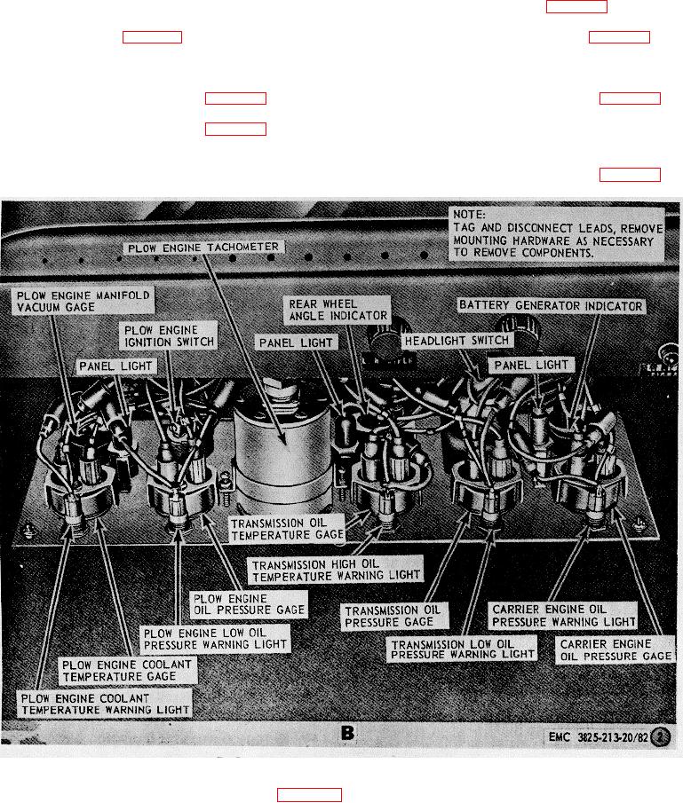
and replace a defective or damaged indicator.
valve assembly as illustrated in figure 83.
c. Installation. Install the battery generator
e. Installation. Install the windshield wiper
indicator as illustrated in figure 82.
control valve assembly as illustrated in figure 82.
150. Windshield Wiper Control Valve Assembly
151. Carrier Engine Throttle Control Assembly
a. Removal. Remove the windshield wiper
a. Removal.
Remove the carrier engine
control valve assembly as illustrated in figure 82.
throttle control assembly as illustrated in figure 82.
b. Disassembly.
b. Cleaning and Inspection. Clean, inspect,
Disassemble the wiper
control valve assembly as illustrated in figure 83.
and replace a defective carrier engine throttle control
c. Cleaning and Inspection. Clean, inspect,
assembly.
c. Installation.
Install the carrier engine
and replace a defective or damaged wiper control valve
throttle control assembly as illustrated in figure 82.
assembly as necessary.
B. Instrument panel, left side, rear view
Figure 82-Continued.
122