
TM 5-3825-213-20
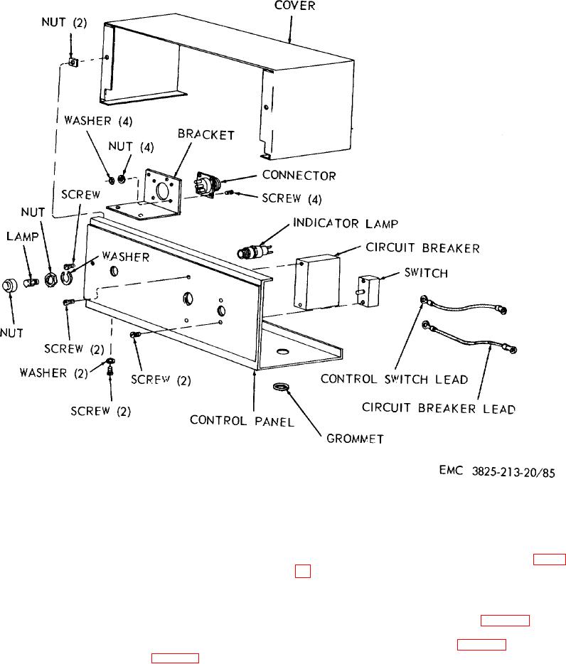
Figure 85. Personnel heater control box, disassembly and reassembly, exploded view.
Section IV. PLOW AND CARRIER ENGINES COOLING SYSTEM
b. Disassembly.
Disassemble the water
161. General
manifold and thermostat housing as illustrated in figure
The plow and carrier engines are liquid cooled.
The coolant is circulated from the radiator through the
c. Cleaning, Inspection, and Repair. Clean
water pump, water manifold, cylinder block, oil cooler,
and inspect all parts and replace as necessary.
and intake manifold back to the radiator.
d. Reassembly.
Reassemble the water
manifold and thermostat as illustrated in figure 86.
162. Plow and Carrier Engine Thermostat Housing
e. Installation. Install the water manifold and
and Water Manifold
thermostat housing as illustrated in figure 75.
a. Removal. Remove the thermostat housing
and water manifold as illustrated in figure 75.
127