
TM 5-3825-213-20
B
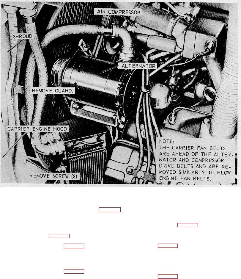
EMC 3825-213-20/87 (2)
B. Carrier engine
Figure 87-Continued.
e. Installation.
Install the radiator shutter
167.
Plow and Carrier Engine Radiator Shutter
assembly as illustrated in figure 88.
Assembly
a. Removal. Remove the radiator shutter
168. Plow and Carrier Engine Oil Cooler and Lines
assembly as illustrated in figure 88.
a. Removal. Remove the lines and oil cooler
b. Disassembly.
Disassemble the radiator
as illustrated in figure 46.
shutter assembly as illustrated in figure 89.
b. Cleaning and Inspection. Clean the lines
c. Cleaning, Inspection, and Repair. Clean all
and cooler and inspect for restricted flow through cooler
parts and inspect for bends, breaks, wear, or other
and damaged housing and threads. Replace defective
damage. Replace defective parts as necessary.
parts as necessary.
d. Reassembly.
Reassemble the radiator
c. Installation. Install the oil cooler and lines
shutter assembly as illustrated in figure 89.
as illustrated in figure 46.
130