
TM 5-3825-213-20
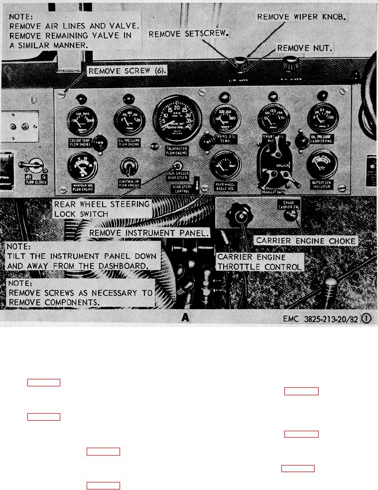
A. Instrument panel, left side, front view
Figure 82. Instrument panel and instruments, removal and installation
146. Panel Light
a. Removal.
148. Headlight Switch Assembly
Remove the panel light as
a. Removal. Remove the headlight switch
illustrated in figure 79.
b. Cleaning and Inspection. Clean, inspect,
assembly as illustrated in figure 82.
b. Cleaning and Inspection. Clean, inspect,
and replace a defective panel light as necessary.
c. Installation.
Install the panel light as
and replace a defective or damaged headlight switch
assembly.
illustrated in figure 79.
c. Installation. Install the headlight switch
assembly as illustrated in figure 82.
147. Rear Wheel Steering Angle Indicator
a. Removal. Remove the rear wheel steering
149. Battery Generator Indicator
angle indicator as illustrated in figure 82.
a. Removal. Remove the battery generator
b. Cleaning and Inspection. Clean, inspect,
indicator as illustrated in figure 82.
and replace a defective angle indicator as necessary.
c. Installation. Install the rear wheel steering
angle indicator as illustrated in figure 82.
121