
TM 5-3825-213-20
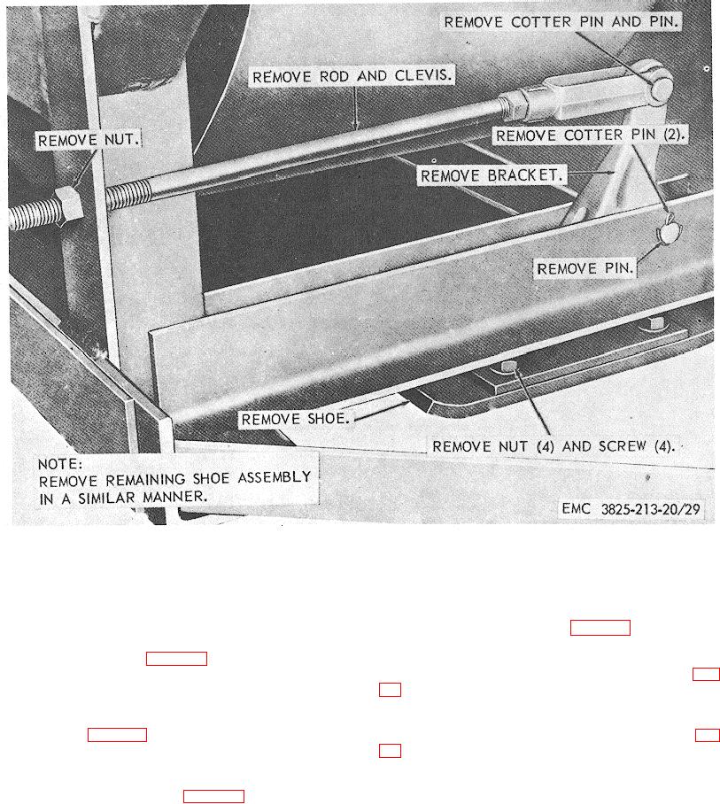
Figure 29. Shoe assembly removal and installation.
b. Cleaning and Inspection. Clean and inspect
d. Adjustment. Adjust the shoe (TM 5-3825-
213-10).
the drive shaft guard and replace as necessary.
c. Installation. Install the auger drive shaft
guard assembly as illustrated in figure 31.
81. Plow Skate Assembly
a. Removal.
Remove the plow skate
83. Plow Lifting Eye
assembly as illustrated in figure 30.
b. Cleaning, Inspection, and Repair. Clean
a. Removal. Remove the plow lifting eye (fig.
and inspect the plow skate as necessary. Repair or
b. Cleaning and Inspection. Clean and inspect
replace as necessary.
c. Installation. Install the plow skate assembly
the plow lifting eye and replace as necessary.
c. Installation. Install the plow lifting eye (fig.
as illustrated in figure 30.
82. Auger Drive Shaft Guard Assembly
a. Removal. Remove the auger drive shaft
guard assembly as illustrated in figure 31.
57