
TM 5-3825-213-20
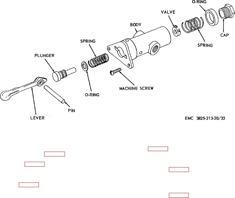
Figure 33. Clutch air valve assembly, diassembly and reassembly, exploded view.
c. Installation.
(4) Replace defective parts as necessary.
Install the cutting edge as
d. Reassembly. Reassemble the drive shaft
illustrated in figure 38.
assembly as illustrated in figure 37.
e. Installation. Install the drive shaft assembly
89. Plow Transmission Linkage
as illustrated in figure 36.
a. Removal. Remove the plow transmission
linkage as illustrated in figure 39.
b. Cleaning, Inspection, and Repair. Clean,
88. Plow Cutting Edge
a. Removal. Remove the cutting edge as
inspect, repair, or replace defective plow transmission
illustrated in figure 38.
linkage.
b. Cleaning and Inspection. Clean, inspect,
c. Installation. Install the plow transmission
and replace a defective cutting edge as necessary.
linkage as illustrated in figure 39.
61