
TM 5-3825-213-35
1
Cap
12
Stop
2
Preformed packing
13
Screw, machine, 1/4-20 x 1/2 in.
3
Valve
14
Washer, lock, 1/4 in.
4
Lock
15
Metering stem
5
Filter
16
Spring retainer
6
Rod
17
Spring
7
Push rod end
18
Piston
8
Nut, 3/8-24
19
Preformed packing
9
Boot
20
Preformed packing
10
Screw, machine, 5/16-18 x 13/16 in. (3 rqr)
21
Spring
11
Flange
22
Body
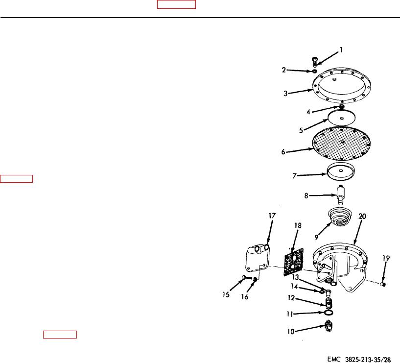
Figure 27. - Continued.
Section V. QUICK RELEASE VALVE ASSEMBLY
125. General
The quick release valve assembly is located above
the rear differential mounted on the carrier frame. The
quick release valve 'is actuated when the treadle valve
is fully or partially released.
126. Quick Release Valve Assembly Removal and
Disassembly
a. Removal. Remove the quick release valve
assembly (TM 5-3825-213-20).
b. Disassembly. Disassemble the quick release
valve assembly in numerical sequence as illustrated on
127.
Quick Release Valve Assembly Cleaning,
Inspection, and Repair
a. Cleaning. Clean all parts with an approved
cleaning solvent and dry thoroughly.
b. Inspection and Repair. Inspect all parts for
defective condition. Replace or repair worn, damaged,
or defective parts.
128. Quick Release Valve Assembly Reassembly
and Installation
a. Reassembly. Reassemble the quick release
valve assembly in reverse of numerical sequence
illustrated on figure 28.
b. Installation. Install the quick release valve (TM
5-3825-213-20).
Figure 28. Quick release valve assembly,
disassembly and reassembly, exploded view.
82