
TM 5-3825-213-35
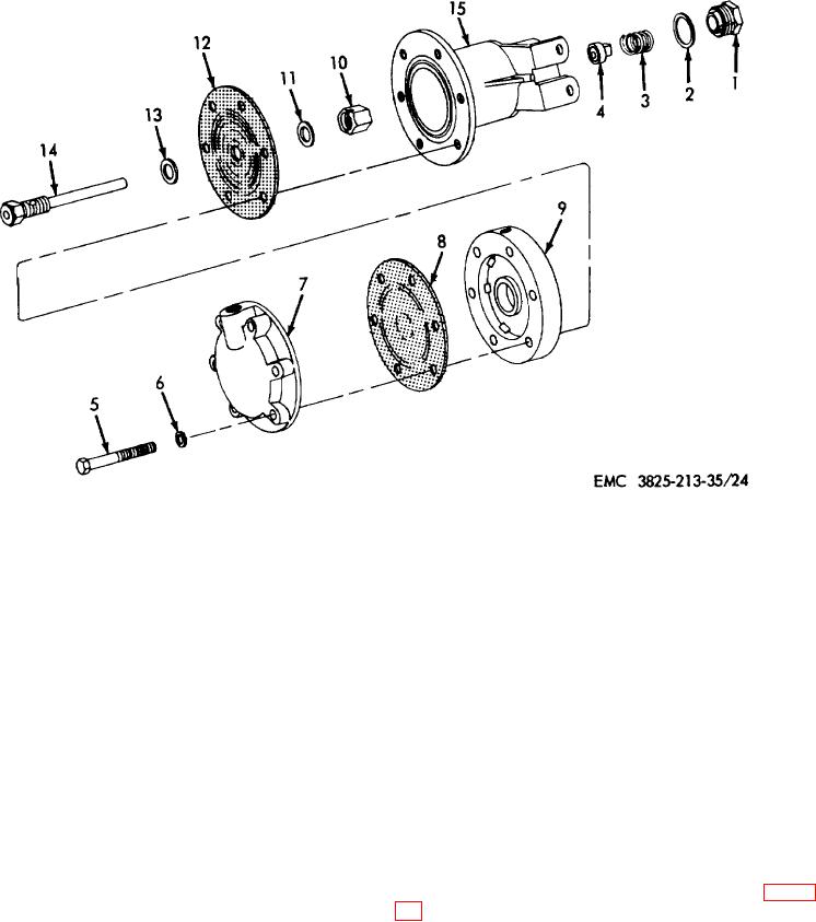
1
Cap
9
Upper housing
2
Gasket
10
Nut, special
3
Spring
11
Washer, flat, brass, special
4
Valve
12
Diaphragm
5
Screw, cap, 1/4-20 x 1 5/8 in. (6 rqr)
13
Washer, flat, brass, special
6
Washer, lock, 1/4 in. (6 rqr)
14
Valve
7
Lower housing
15
Body
8
Diaphragm
Figure 24. Moisture ejector valve assembly, disassembly and reassembly, exploded view.
Section III. THROTTLE CYLINDER AND THROTTLE VALVE ASSEMBLY
114. General
115.
Throttle Cylinder Assembly Removal and
Disassembly
The throttle cylinder assembly is located on the
carrier engine connected to the carburetor assembly.
a. Removal.
Remove
the
throttle
cylinder
The throttle cylinder is an air actuated cylinder. Air
assembly (TM 5-3825-213-20).
pressure applied to the cylinder is proportional to the
b. Disassembly. Disassemble the throttle cylinder
position of the throttle valve.
assembly in numerical sequence as illustrated on figure
77