
TM 5-3825-213-35
1
Nut, 3/8-24
19
Screw, machine, 8-32 x 3/8 in.
2
Washer, lock, ET, 3/8 in.
20
Washer, lock, No. 8
3
Bracket
21
Clamp
4
Dial
22
Ignition coil capacitor
5
Screw, machine, 10-32 x 3/8 in. (8 rqr)
23
Ignition coil capacitor spring
6
Washer, lock, No. 10 (8 rqr)
24
Screw, machine, 10-32 x 3/8 in. (2 rqr)
7
Cover
25
Washer, lock, No. 10 (2 rqr)
8
Gasket
26
Coil holddown plate
9
Plug
27
Coil
10
Screw, machine, 10-32 x 1/4 in. (4 rqr)
28
Gasket
11
Washer, lock, No. 10 (4 rqr)
29
Nut, 832
12
Washer, flat, No. 10 (4 rqr)
30
Washer, lock, No. 8
13
Distributor cap
31
Screw, machine, 6-32 (4 rqr)
14
Gasket (8 rqr)
32
Washer lock No. 6 (4 rqr)
15
Brush
33
Terminal coupling
16
Spring
34
Gasket
17
Nut, 132 (2 rqr)
35
Capacitor
18
Washer, lock, special (2 rqr)
36
Capacitor spring
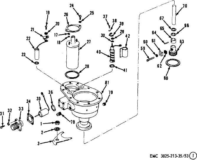
Figure 53. Plow and carrier engine distributor assemblies,
disassembly and reassembly, exploded view.
134