Home
Download PDF
Order CD-ROM
Order in Print
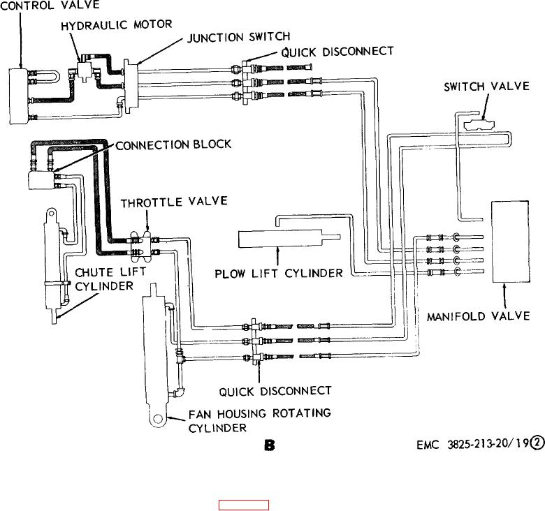
Figure 19. Plow hydraulic oil lines and hose diagram.
Figure 20. Fan housing hydraulic cylinder assembly, removal and installation.
Maintenance Manual Snow Removal Unit, Self-Propelled: Gasoline Driven; Rotary; Wheel Mtd; Winterized
Page Navigation
37
38
39
40
41
42
43
44
45
46
47
TM
5-3825-213-20
B.
Line
diagram
pump-to-components.
Figure
19-Continued.
46