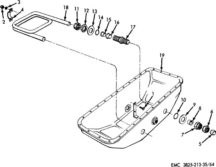
• Home
  • Download PDF
  • Order CD-ROM
  • Order in Print
Figure 63. Plow and carrier engine lower oil pan, oil pump, pickup screen, and upper oil pan assemblies, removal and installation.
Figure 65. Plow and carrier engine oil pump assemblies, disassembly and reassembly, exploded view.

Field Maintenance Manual Snow Removal Unit, Self-Propelled: Gasoline Driven; Rotary; Wheel Mtd; Winterized Page Navigation
  149    150    151    152    153  154  155    156    157    158    159  
img
TM 5-3825-213-35
1
Screw, cap, 3/8-24 x 1 in. (2 rqr)
11
Nut, special (2 rqr)
2
Nut, 3/8-24 (2 rqr)
12
Nut, lock (2 rqr)
3
Washer, lock, 3/8 in. (2 rqr)
13
Washer, special (2 rqr)
4
Bracket
14
Preformed packing (2 rqr)
5
Ferrule (2 rqr)
15
Ferrule (2 rqr)
6
Adapter (2 rqr)
16
Ferrule (2 rqr)
7
Nut, special (2 rqr)
17
Coupling (2 rqr)
8
Ferrule (2 rqr)
18
Heating tube
9
Washer, special (2 rqr)
19
Lower oil pan
10
Preformed packing (2 rqr)
Figure 64. Plow and carrier engine lower oil pans, disassembly and reassembly, exploded view.
160


Privacy Statement
Press Release
Contact

© Copyright Integrated Publishing, Inc.. All Rights Reserved.