
TM 5-3825-213-20
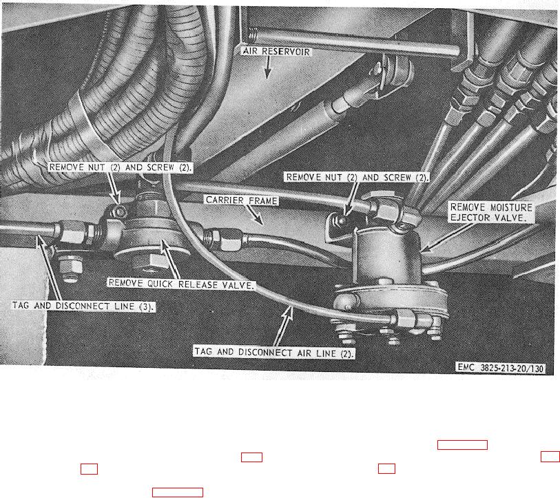
Figure 130. Moisture ejector and quick release valve assemblies,
removal and installation.
(1) Install the air compressor drive belts as
227. Air Compressor Drive Belts
illustrated in figure 136.
a. Removal.
(2) Install the carrier engine fan belts (fig.
(1) Remove carrier engine fan belts (fig.
(2) Remove the air compressor drive belts
Note.
Adjust the drive belts to proper
as illustrated in figure 136.
b. Cleaning and Inspection. Clean the belts.
tension (TM 5-3825-213-10).
Replace defective belts.
c. Installation.
188