
TM 5-3825-212-20
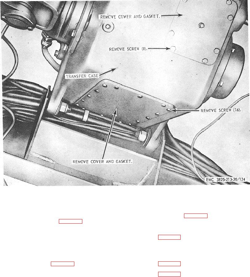
Figure 124. Transfer case inspection covers, removal and installation.
Section V. CARRIER AIR SYSTEM
assembly as illustrated in figure 126.
211. General
The air system (fig.
125) includes the
213. Air Compressor Unloader Valve
compressor, which is driven by the carrier engine, the air
a. Removal. Remove the unloader valve as
receiver tanks, and the lines and hose which connect the
compressor, tanks, and all other air-operated
illustrated in figure 127.
b. Cleaning and Inspection. Clean and inspect
components of the snow removal unit.
all parts. Replace a defective unloader valve and spring
as necessary.
212. Alcohol Injector Assembly
c. Installation. Install the unloader valve as
a. Removal. Remove the alcohol injector
illustrated in figure 127.
assembly as illustrated in figure 126.
d. Adjustment. Adjust the unloader valve as
b. Cleaning and Inspection. Clean and inspect
illustrated in figure 127.
all parts. Replace a defective alcohol injector assembly.
c. Installation.
Install the alcohol injector
182