
TM 5-3825-213-20
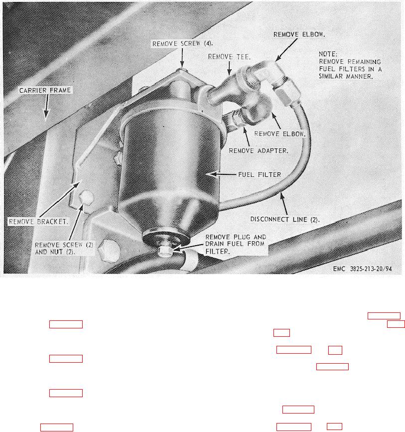
Figure 94. Plow and carrier engine fuel filter, fittings, and bracket, removal and installation.
a.
Removal.
176. Plow and Carrier Engine Fuel Pump Assembly
(1) Remove the water manifold (par. 165).
a. Removal. Remove the fuel pump assembly
(2) Remove the exhaust manifold (par.
as illustrated in figure 95.
b. Cleaning and Inspection. Clean and inspect
(3) Remove the carburetor and governor
all parts. Replace defective parts.
(pars. 174 and 183).
c. Installation. Install the fuel pump assembly
(4) Remove the intake manifold as
as illustrated in figure 95.
illustrated in figure 97.
b. Cleaning and Inspection. Clean and inspect
177. Plow and Carrier Engine Priming Assembly
all parts. Replace defective parts.
a. Removal. Remove the priming assembly
c. Installation.
as illustrated in figure 96.
(1) Install the intake manifold as illustrated
b. Cleaning, Inspection, and Repair. Clean
in figure 97.
and inspect all parts. Replace defective parts.
(2) Install the carburetor and governor
c. Installation. Install the priming assembly as
(pars. 174 and 183).
illustrated in figure 96.
178. Plow and Carrier Engine Intake Manifold
139