
TM 5-3825-213-20
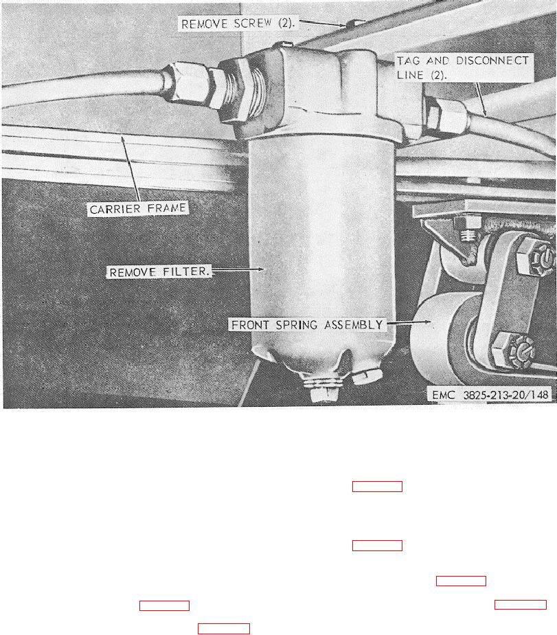
Figure 148. Steering hydraulic oil filter, removal and installation.
Section VIII. CARRIER PERSONNEL HEATER
b. Disassembly. Disassemble the air duct as
240. General
illustrated in figure 151.
The personnel heater is a gasoline-operated,
c. Cleaning, Inspection, and Repair. Clean
thermostatically controlled heater, heating the operator's
and inspect. Replace or repair damaged air ducts,
cab, the battery box, and supplying heat for defrosting
shields, and deflectors as necessary.
the windshield and side panel windows. The battery box
d. Reassembly. Reassemble the air ducts as
temperature is thermostatically controlled.
illustrated in figure 151.
e. Installation.
241.
Personnel Heater, Air Ducts, Shields, and
(1) Install the personnel heater as
Deflector
illustrated in figure 149.
a. Removal.
(2) Install the air ducts, shields, and
(1) Remove the personnel heater as
deflectors as illustrated in figure 150.
illustrated in figure 149.
(2) Remove the air ducts, shields, and
deflectors as illustrated in figure 150.
208