
TM 5-3825-213-20
C
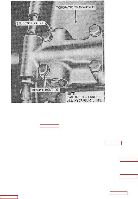
EMC 3825-213-20/142 (2)
C. Selector valve removal points
Figure 142-Continued.
Section VII. CARRIER STEERING HYDRAULIC SYSTEM
and lines as illustrated in figure 143.
233. General
The hydraulic steering unit on the carrier is
235. Hydraulic Pump Assembly
provided to assist the mechanical steering mechanism.
a. Removal. Remove the hydraulic pump
The hydraulic steering unit enables the operator to have
greater control of the vehicle under adverse operating or
assembly and lines as illustrated in figure 144.
b. Cleaning and Inspection. Clean, inspect,
road conditions. The carrier is also equipped with rear
wheel steering to aid in steering on sharp-angle turns.
and replace a defective hydraulic pump.
The complete hydraulic steering system consists of the
c. Installation.
Install the hydraulic pump
hydraulic pump, cylinders, control valve, lines, fittings,
assembly and lines as illustrated in figure 144.
and hydraulic reservoir.
236. Front Steering Control Valve
234. Hydraulic Reservoir
a. Removal.
Remove the front steering
a. Removal. Remove the hydraulic reservoir
control valve as illustrated in figure 145.
and lines as illustrated in figure 143.
b. Cleaning and Inspection. Clean, inspect,
b. Cleaning and Inspection.
Clean and
and replace a defective steering control valve as
inspect. Replace a damaged hydraulic reservoir as
necessary.
necessary.
c. Installation. Install the hydraulic reservoir
202